In this article, we’re looking at sensors that can be used to detect physical intrusion. We will be looking at the following types of sensors:
To monitor output from the sensors, we will be using a UNO R3 microcontroller. This is compatible with the Arduino IDE. If your using Ubuntu as your host system, the Arduino IDE can be installed from the software center.
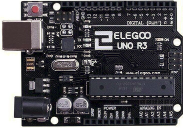
These microcontrollers are programmed using Wiring, which is essentially a set of C++ libraries.
Monitoring Sensor Output
We will be monitoring output from the sensors in two ways, using a buzzer connected to the microcontroller, and via the USB serial interface.
Start by connecting an active buzzer to GPIO pin 13, so we can get some feedback on when the sensors trigger.
| UNO R3 | Active Buzzer |
|---|---|
| GND | Negative |
| GPIO 13 | Positive |
The following code will display the output from the micro controllers serial interface.
import serial
import time

serial_port = '/dev/ttyACM0'
baud_rate = 9600
timeout = 1

ser = serial.Serial(serial_port, baud_rate, timeout=timeout)

def release_the_dogs():
    print("w00f") # Take some form of action here

def monitor_serial():
    print(f"Monitoring data on {serial_port} at {baud_rate} baud...")

    while True:
        if ser.in_waiting > 0:
            data = ser.readline().decode('utf-8').strip()
            if data:
                print(f"Received: {data}")
                if "Intruder Alert!" in data:
                    release_the_dogs()
        else:
            time.sleep(0.1)

try:
    monitor_serial()
except KeyboardInterrupt:
    print("\nMonitoring stopped.")
finally:
    ser.close()
    print("Serial port closed.")
When we have a sensor connected, we should get output.
python3 monitor_serial.py
Monitoring data on /dev/ttyACM0 at 9600 baud...
Received: Intruder Alert!
w00f
Magnetic Contact Sensors
Contact sensors are often used on doors or windows. They are compromised of a reed switch, and a magnet. When the magnet is close enough to the reed switch the contacts inside the reed switch will come together forming a circuit.
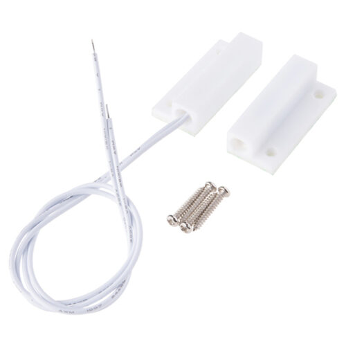
Since this is just acting as a switch, it doesn’t really matter which way round we connect this.
| UNO R3 | Contact Sensor |
|---|---|
| GND | Negative |
| GPIO 12 | Positive |
The following code will generate an alarm when the door opens.
#define BUZZER_PIN 13
#define INPUT_PIN 12

int state; // 0 = closed, 1 = open

void alarm() {
  digitalWrite(BUZZER_PIN, HIGH);
  Serial.println("Intruder Alert!");
  delay(5000);
  digitalWrite(BUZZER_PIN, LOW);
}

void setup()
{
  pinMode(BUZZER_PIN, OUTPUT);
  pinMode(INPUT_PIN, INPUT_PULLUP);
  Serial.begin(9600);
}

void loop()
{
  state = digitalRead(INPUT_PIN);

  if (state == HIGH){
        digitalWrite(BUZZER_PIN, HIGH);
        alarm();
  }
  else{
        digitalWrite(BUZZER_PIN, LOW);
  }
  delay(200);
}
Every time the door is opened, our alarm will trigger.
11:01:45.284 -> Intruder Alert!
11:01:50.513 -> Intruder Alert!
11:01:55.708 -> Intruder Alert!
If an adversary is aware of a reed switch being in place, they could introduce their own magnetic field to trick the sensor into thinking the door is still closed.
Passive Infrared
A passive infrared sensor detects infrared radiation, typically emitted by warm objects such as humans or animals. It’s passive because it does not emit any radiation of its own. It only detects the infrared radiation emitted or reflected by objects in its field of view.
We will be using a HC-SR501 passive infrared module.
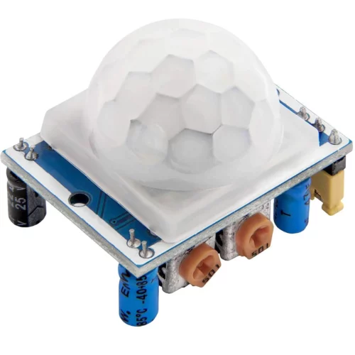
The sensor can be pretty sensitive, with the smallest movement setting it off. Because of this, we sample input from the sensor to see if it’s observed 30 movements within a 10 second window.
The sensor has three pins on it’s underside. Assuming the pins are at the bottom as you look at it, power is left, the trigger (output) is center, and ground is on the right.
| UNO R3 | HC-SR501 |
|---|---|
| GND | GND |
| 5V Power | VCC |
| GPIO 12 | TRIG |
#define BUZZER_PIN 13
#define INPUT_PIN 12

int pirState = LOW;
int val = 0;

unsigned long lastMotionTime = 0;  // Stores the time of the last motion detection
int motionCount = 0;               // Count of motion detections within the 10-second window

void setup() {
  pinMode(BUZZER_PIN, OUTPUT);
  pinMode(INPUT_PIN, INPUT);

  Serial.begin(9600);
}

void alarm() {
  digitalWrite(BUZZER_PIN, HIGH);
  Serial.println("Intruder Alert!");
  delay(5000);
  digitalWrite(BUZZER_PIN, LOW);
}

void loop() {
  val = digitalRead(INPUT_PIN);

  if (val == HIGH) {  // Motion detected
    if (millis() - lastMotionTime <= 10000) {  // Check if motion occurred within 10 seconds
      motionCount++;
    } else {
      Serial.println("Resetting");
      motionCount = 1;  // Reset counter if 10 seconds have passed
    }

    lastMotionTime = millis();  // Update the last motion time

    Serial.print("Motion Count: ");
    Serial.println(motionCount);

    if (motionCount >= 30) {
      alarm();
      motionCount = 0;
    }
  }

  delay(100);
}
Running the code, we should only get alarms when it detects multiple instances of motion in a short period.
09:46:57.288 -> Motion Count: 18
09:46:57.387 -> Motion Count: 19
09:46:57.486 -> Motion Count: 20
09:46:57.586 -> Motion Count: 21
09:46:57.685 -> Motion Count: 22
09:47:02.788 -> Motion Count: 23
09:47:02.888 -> Motion Count: 24
09:47:02.987 -> Motion Count: 25
09:47:03.086 -> Motion Count: 26
09:47:03.185 -> Motion Count: 27
09:47:03.318 -> Motion Count: 28
09:47:03.417 -> Motion Count: 29
09:47:03.516 -> Motion Count: 30
09:47:03.516 -> Intruder Alert!
It’s likely other passive infrared sensors use a similar algorithm to ensure the alarm does not cause too many false positives. As such, moving very slowly may evade the alarm.
Ultrasonic Detection
Ultrasonic sensors work by emitting high-frequency sound waves (ultrasonic waves) and measuring the time it takes for the waves to reflect off an object and return to the sensor. This allows us to measure distance.
We will be using a HC-SR04 ranging module which can detect distances up to 400cm, with a 30 degree cone of vision. Ultrasonic sensors are best used when you want to monitor the existence of a particular item.
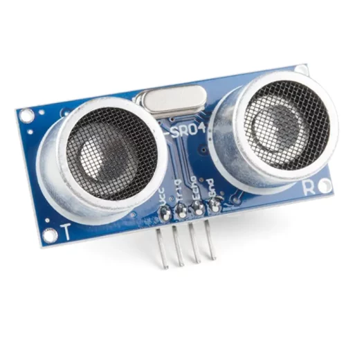
Luckily, the ports on the sensor are labeled. Connect it to the microcontroller using the following:
| UNO R3 | HC-SR04 |
|---|---|
| GND | GND |
| 5V Power | VCC |
| GPIO 12 | TRIG |
| GPIO 11 | ECHO |
#include "SR04.h"
#define TRIG_PIN 12
#define ECHO_PIN 11
#define BUZZER_PIN 13

SR04 sr04 = SR04(ECHO_PIN,TRIG_PIN);
long a;

void setup() {
   pinMode(BUZZER_PIN, OUTPUT);
   Serial.begin(9600);
   delay(1000);
}

void loop() {
   a=sr04.Distance();
   Serial.print(a);
   Serial.println(" cm");
   if (a < 50)
   {
      digitalWrite(BUZZER_PIN, LOW);
      Serial.println("Intruder alert!");
      digitalWrite(BUZZER_PIN, HIGH);
   }
   else {
      digitalWrite(BUZZER_PIN, LOW);
    }
   delay(2000);
}
If anything gets within 50cm of our sensor, the alarm will trigger.
13:42:30.850 -> 62 cm
13:42:32.869 -> 61 cm
13:42:34.921 -> 62 cm
13:42:36.941 -> 64 cm
13:42:38.993 -> 63 cm
13:42:41.011 -> 9 cm
13:42:41.011 -> Intruder alert!
13:42:43.029 -> 63 cm
13:42:45.081 -> 61 cm
Lasers
To create a laser tripwire, we just need a laser emitter and a photodetector. If the beam of light between the emitter and the photodetector is severed, we know we have an intruder.
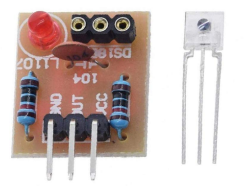
We will be using a HW 493 laser, pictured below.

And a DS18B20 sensor.
Connect the components to the microcontroller using the following pins. Note, the UNO R3 only has one 5V out, so you will need to use a breadboard to split it between the two devices.
| UNO R3 | HW 493 |
|---|---|
| GND | GND |
| 5V Power | VCC |
| GPIO 12 | S |
| UNO R3 | DS18B20 |
|---|---|
| GND | GND |
| 5V Power | VCC |
| GPIO 11 | OUT |
#define BUZZER_PIN 13
#define LASERPIN 12
#define SENSORPIN 11

int LaserSensor = 11;
int SensorReading = HIGH;

void setup() {
  pinMode(BUZZER_PIN, OUTPUT);
  pinMode(LASERPIN, OUTPUT);
  pinMode(SENSORPIN, INPUT);
  Serial.begin(9600);
}

void alarm() {
  digitalWrite(BUZZER_PIN, HIGH);
  Serial.println("Intruder Alert!");
  delay(1000);
  digitalWrite(BUZZER_PIN, LOW);
}


void loop() {
  digitalWrite(LASERPIN, HIGH);
  delay(200);

  SensorReading = digitalRead(SENSORPIN);
  if (SensorReading == HIGH)
  {
    alarm();
  }
}
When the laser beam is broken, you should receive alerts.
14:39:12.229 -> Intruder Alert!
To deploy the laser, you have a number of options.
- Run long wires between the emitter and sensor
- Use a mirror to bounce the laser beam back from the emitter to the sensor
- Use a separately powered laser not connected to the microcontroller
An adversary may be able to bypass the system by directing their own laser beam at the photodetector.
In Conclusion
You could interface with these sensors using something like a Raspberry Pi, however microcontrollers are cheaper with much greater battery life so each sensor could have it’s own microcontroller that feeds it’s output to an SBC like the Pi.